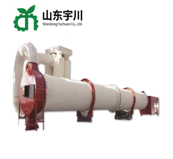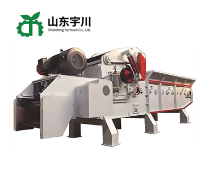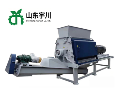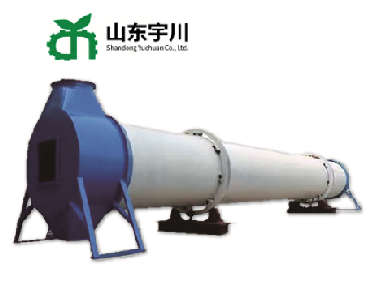
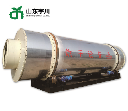
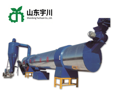
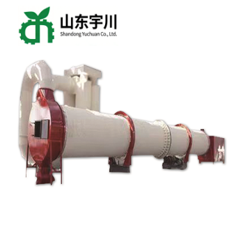
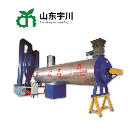
Sawdust, Wood Chips, Biomass Materials Rotary Dryer
Low energy consumption, high thermal efficiency
Even drying, stable finished moisture
Compact structure, small floor space
Wide adaptability for different raw materials
Simple operation and low maintenance cost
Long service life, durable wear parts
1.Product Overview
1.1 The Drying Stage in a Biomass Line
Drying is the stage between crushing and pelletizing, and it decides whether the rest of the line can work at its rated capacity. Wet raw material cannot be compressed into a dense pellet: the moisture forms steam inside the die, the pellet cracks after cooling, and the die and the rollers wear faster. Material that is too dry behaves in the opposite way, generating dust and blocking the feeding section. The usual target is 8% to 12% final moisture, and it has to be held continuously, because the moisture of incoming sawdust, straw or shell changes from load to load.
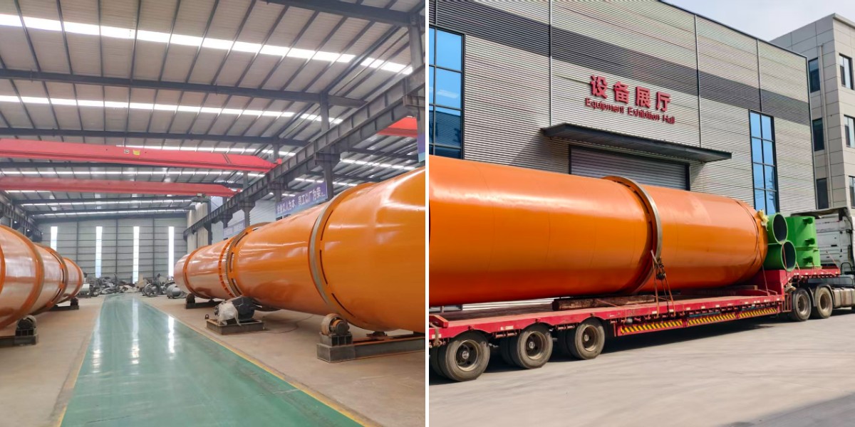
The equipment described in this document is a family of rotary drum dryers that serve this stage. They share the same working principle, that is, wet material is lifted and dropped through a stream of hot air inside a rotating cylinder and is discharged when it is dry enough, but they differ in the arrangement of the drying passes, in the way the heat is used, and in the capacity and floor space they need. The six types listed on the cover are therefore not competing products but a range from which the configuration is selected according to the material, the required evaporation, the available heat source and the space in the workshop.
All types can be completed with a feeding conveyor, a heat source, a cyclone, a bag filter, an airlock discharger and a control cabinet, so that the customer receives a working drying section rather than a bare drum. Voltage, frequency, burner type, drum length and capacity are customized for each market, and the technical data of a given unit is calculated from the material, the initial moisture and the required hourly evaporation instead of being taken from a fixed catalogue line.
1.2 Triple Pass Dryer
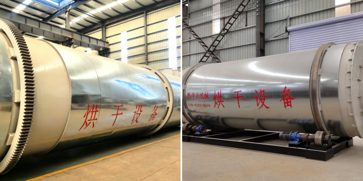
The triple pass dryer is the most widely used type in biomass plants. Three concentric cylinders are arranged inside one shell. Wet material enters the inner cylinder, is lifted and scattered by the internal lifting plates, then passes into the middle cylinder and finally into the outer cylinder, from which it is discharged. The hot air flows in the opposite direction across the three passes, so the air that has already lost part of its heat in the first pass is still used in the second and third passes instead of escaping directly to the chimney.
Because the material travels three passes within the length of one drum, the heat exchange path is about three times that of a single-drum dryer of the same shell length, and the machine takes roughly one third of the floor length of an equivalent single-pass unit. This combination of a long drying path and a short footprint is the reason the type is preferred where the workshop is already built or where the dryer has to be installed indoors next to the pellet mill. The outlet air temperature is comparatively low, which reduces the heat carried away by the exhaust and improves the overall thermal efficiency of the unit.
1.3 Rotary Dryer
The rotary dryer is the single-drum type. One large cylinder, fitted with lifting plates and usually inclined slightly towards the discharge end, carries the material from the inlet to the outlet while hot air passes through it, either in parallel flow or in counter flow. The structure is simple: one shell, two riding rings, a gear ring drive, a heat source and a discharge section.
The advantage of this type is its robust simplicity and its tolerance of difficult material. Very wet, lumpy or abrasive material that would block the narrow passages of a multi-pass drum can be handled in a single large chamber, and the interior is easy to inspect and clean. Its investment cost per unit of evaporation is low, but its heat consumption and its floor length are higher than those of the triple pass type, because the exhaust leaves the drum at a relatively high temperature and the drying path is only the length of one drum. It is normally chosen for mineral, sludge and high-moisture bulk materials, or for plants where floor space is not a constraint.
1.4 Biomass Drying
Biomass drying is not a separate drum design but a complete drying system configured for biomass raw material. In this configuration one of the drum types above, usually the triple pass or the third generation type, is combined with a biomass burner fired with the plant own wood residue, a feeding section that can accept fibrous and light material, a cyclone and a bag filter at the discharge, and a control system that holds the outlet moisture at the value required by the pellet mill.
The point of this configuration is that the fuel for drying comes from the process itself: bark, sawdust, offcuts and rejects that cannot be sold as product are burned to dry the material that will be sold as pellets. The external energy input of the drying stage is therefore limited to the electricity of the drum drive, the fan and the feeding equipment, and the fuel cost is close to zero for a plant that already has residue. This is why the biomass drying configuration is normally quoted together with a crusher, a pellet mill and a cooling section rather than as a stand-alone machine.
1.5 Third Generation High-Efficiency Energy-Saving Dryer
The third generation high-efficiency energy-saving dryer is the current development of the triple pass principle. The three-pass layout is retained, but the air flow, the lifting plate geometry, the sealing of the drum ends and the insulation have been redesigned so that a larger share of the heat supplied by the burner is transferred to the material instead of being lost through the shell or carried out with the exhaust.
Compared with earlier generations, the lifting plates are arranged at different angles in each pass so that the material curtain meets the air stream at the most effective point, the drum ends are sealed to limit the infiltration of cold air, the outer shell is insulated and clad, and the drive is fitted with a variable-frequency control so that the residence time can follow the moisture of the incoming material. The result is a machine that reaches the required outlet moisture with less fuel per tonne and a more uniform final product, which matters most where fuel has to be purchased rather than taken from the plant residue.
1.6 Combination Multi-Channel Dryer
The combination multi-channel dryer divides the interior of the drum into several parallel channels, each with its own lifting arrangement and its own position in the air stream. Material entering the drum is split between the channels and travels through them at the same time, and the channels can be arranged so that the material passes through a high-temperature drying zone and then a lower-temperature equalizing zone before discharge.
This arrangement is used where a single pass would be either too long or too uneven. It suits plants with a large hourly evaporation, material whose initial moisture varies widely between loads, and mixtures of different materials fed to the same line, because the residence time in each channel can be balanced against the others. The multi-channel layout also makes the temperature profile inside the drum controllable: the first channel removes the surface moisture quickly, the following channels equalize the moisture through the particle, and the final channel brings the material to the discharge moisture without overheating it.
1.7 Energy-Saving Dryer
The energy-saving dryer is the economical configuration of the same drum principle, intended for small and medium plants where fuel or power is expensive and the budget does not allow a fully automated drying section. Its energy-saving measures are concentrated on the points where loss is easiest to avoid: an insulated shell, a sealed discharge section, a correctly matched fan, a variable-frequency drive on the drum and the feeding equipment, and recovery of part of the exhaust heat for preheating the incoming air or the material.
The machine is simpler than the third generation type and easier to maintain with local labor, which is important in plants far from a service center. It is normally supplied with a manual or semi-automatic control of the burner and the drum speed, and it can be upgraded later with a burner control and a moisture meter if the plant expands.
1.8 How the Type Is Selected
Selection starts from three figures: the material and its initial moisture, the hourly evaporation that has to be achieved, and the heat source that is available at site. With these, the drum diameter and length are calculated, and the type is then chosen against the constraints of the project. Where floor length is limited and the material is biomass, the triple pass or the third generation type is preferred; where the material is very wet, lumpy or abrasive, the single-drum rotary dryer is more tolerant; where the evaporation is large or the moisture varies widely, the multi-channel type gives a more even result; where fuel cost dominates and the budget is limited, the energy-saving configuration is the practical choice.
In every case the quotation is based on the working conditions supplied by the customer rather than on a nominal capacity, because the evaporation of a drum depends on the difference between inlet and outlet moisture, on the inlet air temperature and on the specific heat of the material. A drum sized for sawdust at 35% initial moisture will not reach the same output on straw at 50%, and a dryer quoted without these figures is a dryer that will be either oversized or short of capacity in operation.
2. Key Advantages of the Dryer
2.1 Advantages Common to the Whole Series
The points below apply to all six types, because they come from the same design principles: a rotating drum, internal lifting plates, a matched air flow and a dust collection at the discharge.
1. Heat is used more than once. In the multi-pass and multi-channel types the exhaust of one pass is the drying air of the next, so the heat that would otherwise leave through the chimney continues to evaporate moisture.
2. The shell is insulated and clad with a steel jacket, which limits heat loss through the wall, keeps the outer surface at a temperature safe for operators and reduces fuel consumption for the same evaporation.
3. Lifting plates are arranged according to the material flow in each pass, so the material is lifted, scattered and dropped evenly through the hot air and the discharge moisture is uniform instead of varying from wet lumps to over-dried powder.
4. The compact multi-pass layout reduces the floor length required, which saves civil construction cost and allows the dryer to be installed in an existing workshop beside the pellet mill.
5. Drum speed is controlled by a variable-frequency drive, so the residence time can be matched to the initial moisture of the incoming material without changing the drum or the heat source.
6. The heat source is flexible: a biomass burner fired with the plant own residue, a gas or oil burner, or waste heat from a boiler or kiln. The customer can therefore use the cheapest energy available at site.
7. The drum runs on machined riding rings and hardened support rollers with a gear ring drive, which gives smooth rotation with low vibration and long bearing life.
8. A cyclone and a bag filter at the discharge collect the coarse and the fine fraction respectively, so the exhaust is clean and the dried product is recovered rather than lost.
9. Wearing parts are few and accessible. Inspection doors on the shell allow the lifting plates and the internal structure to be checked, and replacement work does not require dismantling the whole drum.
10. Voltage, frequency, capacity, burner type, feeding arrangement and the level of automation are all customized, so the dryer can be matched to the crusher, the pellet mill and the local working conditions.
2.2 Advantages of Each Type
Triple Pass Dryer. The three concentric passes give a heat exchange path about three times longer than a single drum of the same shell length, with a footprint of roughly one third. The exhaust leaves at a comparatively low temperature, so the heat carried away is small and the thermal efficiency is high. It is the best compromise between efficiency and floor space for biomass material.
Rotary Dryer. One large chamber, no narrow passages, so very wet, lumpy and abrasive material can pass without blocking; the interior is easy to inspect and clean; the investment cost per unit of evaporation is the lowest of the series; and the structure is simple enough to be maintained with local labor.
Biomass Drying. The drying fuel comes from the plant own residue, so the external fuel cost of the drying stage is close to zero; the system is configured together with the crusher and the pellet mill, so the moisture of the material entering the die is held at the value the die needs; and the whole section is supplied as one package with burner, cyclone, filter and controls.
Third Generation High-Efficiency Energy-Saving Dryer. The redesigned air flow and the per-pass lifting plate angles raise the share of the burner heat that reaches the material; the sealed drum ends prevent cold air from entering; the insulated shell limits wall loss; and the variable-frequency drive keeps the outlet moisture stable when the incoming material changes. Fuel per tonne of dried material is the lowest of the triple pass family.
Combination Multi-Channel Dryer. Parallel channels allow a large evaporation in a drum of moderate length, balance the residence time of materials with different moisture, and make the temperature profile inside the drum controllable, so surface moisture is removed quickly without overheating the particle; it suits large plants and mixed or variable feed.
Energy-Saving Dryer. Investment and running cost are concentrated where loss is easiest to avoid: insulation, sealing, matched fan, variable-frequency drive and partial recovery of the exhaust heat. The machine is simple to operate and to maintain, and it can be upgraded later with automatic burner control and a moisture meter.
3. Manufacturing Process
3.1 Common Process
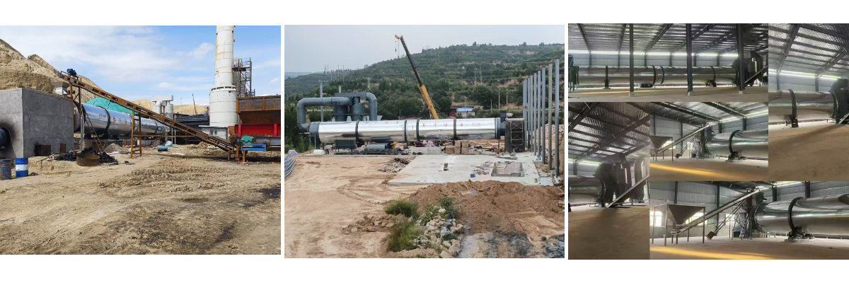
A rotary dryer works under continuous heat and rotation for years, so the cylinder, the riding rings and the concentricity of the passes determine whether the machine will run straight. The production process is controlled at the following stages.
1. Material selection and cutting. Cylinder shells are made of Q235B or Q345R steel plate of certified origin; plates are cut on a CNC plasma cutting machine, the edges are prepared for welding, and each plate is identified so that the heat number can be traced to the finished drum.
2. Rolling and seam welding. Each shell is rolled on a plate rolling machine to the calculated diameter; the longitudinal seam is welded with submerged arc welding and the circumferential seams after the sections are aligned in a fixture, so that the roundness and the straightness stay within tolerance.
3. Weld inspection. Critical seams are checked by penetrant or ultrasonic testing, and the roundness, the straightness and the length of each shell are measured and recorded before assembly.
4. Riding ring and roller machining. Riding rings are forged or rolled from carbon steel, machined and fitted to the shell; support rollers are machined, hardened and ground, so that the drum rotates without runout and the load is shared evenly by the two supports.
5. Gear ring and drive. The transmission gear ring is hobbed and fitted with a pre-loaded fit; the pinion, the reducer and the motor are aligned so that the tooth contact pattern is even under load and the drive runs without shock.
6. Concentric assembly. The passes are assembled with spacer plates and internal supports so that the gap between them is equal along the full length; this gap is what allows material and air to move from one pass to the next without leakage or dead zones.
7. Lifting plate welding. Lifting plates are welded inside each pass at the angles required by the material flow, and their height, spacing and direction are checked so that the material is lifted and scattered but not carried over the top of the pass.
8. Heat source interface. The burner connection, the inlet duct and the discharge hood are fabricated to the drawing, with expansion joints where the temperature difference is large, so that the drum can expand without stressing the ductwork.
9. Insulation and cladding. Rock wool insulation is applied to the outer shell and covered with a steel jacket sealed at both ends, which limits heat loss and protects the insulation from rain and dust.
10. Assembly and no-load test. The drum is assembled on its frame, the drive is connected, and the machine runs without load to check rotation, runout of the riding rings, bearing temperature and noise; the burner and the fan are test-run together with the drum.
11. Load test and drying trial. Where material is available, a trial is run with the customer material to confirm the outlet moisture, the exhaust temperature and the evaporation reached at the design settings, and the results are recorded for the commissioning report.
12. Painting, marking and packing. The frame and the jacket are shot-blasted, primed and top-coated, a nameplate with model, drum speed, motor power and serial number is fitted, and the unit is packed in sections for container transport with the assembly drawing enclosed.
3.2 Special Processes by Type
Triple pass and third generation types. The three shells are assembled so that the annular gap between the passes is equal within the tolerance along the whole length, because an uneven gap concentrates the air flow in one sector and leaves wet material in another. The lifting plates are welded at different angles in each pass, and the whole assembly is checked for concentricity before the outer jacket is closed.
Combination multi-channel type. The internal partition plates are welded to a fixture so that the channels are of equal section, and the partition seams are checked for tightness, because leakage between channels would destroy the intended temperature profile. The channel outlets are then balanced against the air flow measured at the discharge hood.
Energy-saving and biomass drying configurations. The insulation thickness, the sealing of the drum ends and the matching of the fan to the duct resistance are controlled as a set, because the energy saving of these types depends on the three being correct at the same time. The burner is test-fired and its flame adjusted before shipment, and the control cabinet is wired and function-tested with the drum drive and the fan.
4. FAQ
Q1. Which of the six dryer types is right for my plant?
It depends on three figures: the material and its initial moisture, the evaporation required per hour, and the heat source available at site. For biomass material in a workshop with limited floor length, the triple pass or the third generation type is normally recommended; for very wet, lumpy or abrasive material the single-drum rotary dryer is more tolerant; for large evaporation or widely varying moisture the multi-channel type is preferable; and for a limited budget the energy-saving configuration is the practical choice. Please send the three figures and we will calculate the drum and recommend the type.
Q2. What raw materials can be dried?
Sawdust, wood chips, shavings, bark, straw, corn stalk, rice husk, palm kernel shell, copra, corn cob, bamboo, distillers grains, brewer spent grain, manure, compost, paper sludge, sewage sludge, sand, clay and slag fines. Fibrous and light material is easier to dry when it has been crushed to a short, uniform size first.
Q3. What final moisture can be reached?
Normally 8% to 12%, which is the range required for pelletizing and briquetting. The exact value is set during commissioning by the drum speed, the inlet air temperature and the feed rate, and is held by the control system when the incoming material changes.
Q4. What heat source can be used, and which is cheapest?
A biomass burner fired with wood residue from the plant, a gas or oil burner, or waste heat from a boiler or kiln. For a plant that already produces bark, sawdust and offcuts, the biomass burner is the cheapest in running cost because the fuel is residue that would otherwise be wasted; where waste heat is available, it is cheaper still, but its temperature and quantity have to be confirmed before the drum is sized.
Q5. How much does the dryer save compared with a single-drum machine?
The multi-pass and multi-channel types reuse the exhaust heat in the following passes and lose less heat through an insulated shell, so the fuel per tonne of dried material is considerably lower and the exhaust temperature is lower. The exact saving depends on the material, the initial moisture and the heat source, so it is calculated against the customer working conditions before quoting rather than given as a fixed percentage.
Q6. What capacity can be supplied?
Capacity is expressed as hourly evaporation, that is, the tonnes of water removed per hour, and it is calculated from the material, the initial moisture and the required final moisture. Please provide these figures together with the output of the pellet line so that the drum can be sized correctly; the drum diameter and length, the burner rating and the fan are then selected as a set.
Q7. Is dust a problem at the discharge end?
No. A cyclone separates the coarse fraction and a bag filter collects the fine dust, so the exhaust is clean. The collected powder is returned to the product, which also avoids material loss. Where local emission rules are strict, the filter area and the duct design are increased accordingly.
Q8. What maintenance does the dryer need?
Routine lubrication of the support rollers and the gear drive, checking of the riding ring runout, the roller surface and the lifting plates, cleaning of the internal passages, and inspection of the burner and the fan. The inspection doors give access to the shell, and no special tools are required beyond the standard set supplied with the machine.
Q9. How is the dryer installed and commissioned?
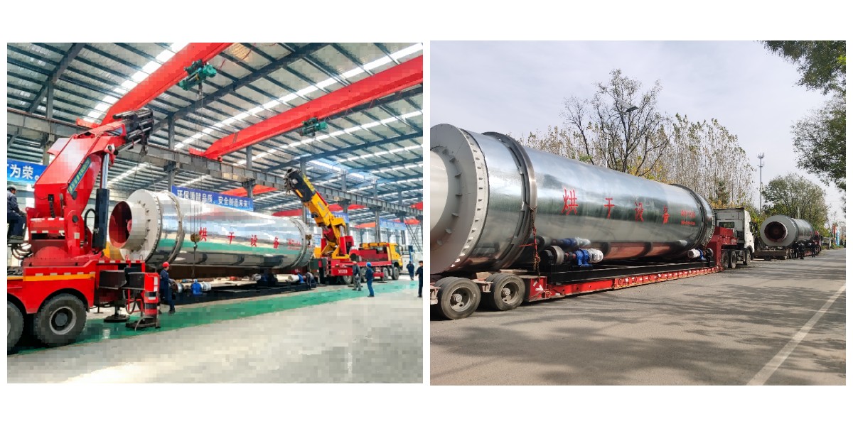
The unit is shipped in sections with an assembly drawing and a foundation plan. Installation requires a level concrete foundation for the frame and the burner, and the drum is aligned on its supports before the drive is connected. Commissioning includes the no-load run, the burner adjustment and a drying trial with the customer material; an engineer can be sent to site when required.
Application Scenarios
No. | Dryer Type | Industry / Field | Wet Raw Material | Drying Purpose and End Product | Usual Heat Source |
1 | Triple Pass Dryer | Biomass pellet plants | Wet sawdust, wood chips, shavings | Moisture to 8-12% for pelletizing; wood pellets | Biomass burner |
2 | Triple Pass Dryer | Palm oil and coconut mills | Wet palm kernel shell, copra, palm fibre | Dry shell and fibre for export pellet fuel | Biomass burner |
3 | Triple Pass Dryer | Rice, grain and crop residue stations | High-moisture rice husk, corn cob, straw | Dry husk, cob and straw for pellet fuel | Biomass burner |
4 | Rotary Dryer | Mineral and chemical plants | Wet sand, clay, slag fines, ore powder | Material dried before grinding, batching or briquetting | Gas or oil burner |
5 | Rotary Dryer | Municipal sludge treatment | Dewatered sewage sludge, paper sludge | Volume and moisture reduced for incineration or reuse | Waste heat or gas burner |
6 | Rotary Dryer | Distillery and brewery plants | Wet distillers grains, brewer spent grain | Dry grains for feed and fuel | Waste heat from boiler |
7 | Biomass Drying | Complete biomass pellet lines | Wet sawdust, bark, offcuts, wood residue | Feedstock dried to die specification; pellets for export | Biomass burner fired with plant residue |
8 | Biomass Drying | Bamboo, charcoal and briquette plants | Wet bamboo scrap, charcoal fines | Dry material for charcoal briquette | Biomass burner |
9 | Biomass Drying | Organic fertilizer plants | Fresh manure, wet compost, straw ash | Dry material for organic fertilizer granulation | Biomass burner or waste heat |
10 | Third Generation High-Efficiency Energy-Saving Dryer | Pellet plants with purchased fuel | Wet sawdust, wood chips, shavings | Stable outlet moisture at the lowest fuel cost per tonne | Biomass, gas or oil burner |
11 | Third Generation High-Efficiency Energy-Saving Dryer | Export pellet producers | Mixed hardwood and softwood residue | Uniform dry material for high-density export pellets | Biomass burner or waste heat |
12 | Third Generation High-Efficiency Energy-Saving Dryer | Paper and packaging mills | Paper trimmings, pulp reject, mill sludge | Waste dried for boiler fuel or disposal | Waste heat from boiler |
13 | Combination Multi-Channel Dryer | Large-capacity pellet plants | Sawdust, chips and shavings of varying moisture | High hourly evaporation with even outlet moisture | Biomass burner |
14 | Combination Multi-Channel Dryer | Mixed-feed briquette plants | Mixed wood waste, straw and shell | Several materials dried in one pass without overheating | Biomass burner |
15 | Combination Multi-Channel Dryer | Chemical and mineral powder lines | Wet chemical powder, mineral fines | Controlled temperature profile; dry powder for batching | Gas burner or waste heat |
16 | Energy-Saving Dryer | Small and medium workshops | Sawdust, shavings, rice husk | Pellets or briquettes with low fuel and power cost | Biomass burner |
17 | Energy-Saving Dryer | Farm-scale and cooperative plants | Straw, corn stalk, manure | Fuel pellets and fertilizer material at low investment | Biomass burner |
18 | Energy-Saving Dryer | Plants with limited power supply | Sawdust, wood powder, charcoal fines | Drying with reduced installed power and running cost | Biomass or gas burner |
Combination multi-channel dryer
| Model | Evaporation Capacity | Driving Power | Matching Fan | Air Lock Discharger | Remarks |
|---|---|---|---|---|---|
| 1.8*18 | 3.0-4.0 | 22 | 45 | 500/3 | Parameters are for reference only, subject to material characteristics |
| 2.2*22 | 5.0-6.0 | 30 | 55 | 600/3 | Parameters are for reference only, subject to material characteristics |
| 2.6*26 | 6.0-7.0 | 37 | 75 | 700/5.5 or larger | Parameters are for reference only, subject to material characteristics |
New combination drum dryer
| Model | Evaporation Capacity | Driving Power | Matching Fan | Air Lock Discharger | Remarks |
|---|---|---|---|---|---|
| 1.2*12 | 0.25-0.45 | 5.5 | 11 | 300/1.5 | Parameters are for reference only, subject to material characteristics |
| 1.5*15 | 0.5-0.7 | 11 | 15 | 400/2.2 | Parameters are for reference only, subject to material characteristics |
| 1.8*18 | 1.0-1.5 | 15 | 22 | 500/3 | Parameters are for reference only, subject to material characteristics |
| 2.2*24 | 2.5-3.5 | 22 | 37 | 600/4 | Parameters are for reference only, subject to material characteristics |
| 2.5*24 | 2.5-4.7 | 22 | 45 | 600/4 | Parameters are for reference only, subject to material characteristics |
| 3.0*30 | 5.0-6.0 | 37 | 75 | 700/5.5 or larger | Parameters are for reference only, subject to material characteristics |
| 3.5*30 | 6.5-8.0 | 45 | 90 | 700/5.5 or larger | Parameters are for reference only, subject to material characteristics |
Double cylinder energy-saving dryer
| Model | Evaporation Capacity | Driving Power | Matching Fan | Air Lock Discharger | Remarks |
|---|---|---|---|---|---|
| 1.2*6 | 0.7-1.0 | 5.5 | 7.5 | 300/2.2 | Parameters are for reference only, subject to material characteristics |
| 1.2*9 | 1.0-1.3 | 7.5 | 11 | 300/2.2 | Parameters are for reference only, subject to material characteristics |
| 1.5*9 | 1.2-1.5 | 11 | 15 | 300/3 | Parameters are for reference only, subject to material characteristics |
Third generation high-efficiency energy-saving dryer
| Model | Evaporation Capacity | Driving Power | Matching Fan | Air Lock Discharger | Remarks |
|---|---|---|---|---|---|
| 1.5*9 | 1.5-2.0 | 11 | 15 | 300/3 | Parameters are for reference only, subject to material characteristics |
| 1.5*13 | 2.0-2.3 | 11 | 15 | 300/3 | Parameters are for reference only, subject to material characteristics |
| 1.8*13 | 2.0-2.7 | 15 | 18.5 | 400/4 | Parameters are for reference only, subject to material characteristics |
| 1.8*18 | 2.5-3.5 | 18.5 | 22 | 400/4 | Parameters are for reference only, subject to material characteristics |
| 2.2*13 | 2.5-3.5 | 18.5 | 22 | 400/4 | Parameters are for reference only, subject to material characteristics |
| 2.2*18 | 4.0-4.5 | 22 | 30 | 500/5.5 | Parameters are for reference only, subject to material characteristics |
| 2.5*18 | 5.0-5.5 | 22 | 45 | 500/5.5 | Parameters are for reference only, subject to material characteristics |
Three return drum dryer
| Model | Evaporation Capacity | Driving Power | Matching Fan | Air Lock Discharger | Remarks |
|---|---|---|---|---|---|
| 2.0*8 | 1.5-2.0 | 4*4 | 30 | 400/2.2 | Parameters are for reference only, subject to material characteristics |
| 2.2*12 | 2.0-3.0 | 4*4 | 55 | 500/3 | Parameters are for reference only, subject to material characteristics |
| 2.5*12 | 3.0-4.0 | 7.5*4 | 75 | 500/3 | Parameters are for reference only, subject to material characteristics |
| 2.8*8 | 3.5-4.5 | 5.5*4 | 75 | 600/3 | Parameters are for reference only, subject to material characteristics |
| 2.8*12 | 3.5-5.0 | 7.5*4 | 90 | 600/3 | Parameters are for reference only, subject to material characteristics |
| 3.0*8 | 4.5-5.5 | 7.5*4 | 75 | 600/3 | Parameters are for reference only, subject to material characteristics |
| 3.0*12 | 5.0-6.0 | 11*4 | 90 | 700/5.5 or larger | Parameters are for reference only, subject to material characteristics |
| 3.2*8 | 5.5-6.5 | 7.5*4 | 90 | 700/5.5 or larger | Parameters are for reference only, subject to material characteristics |
| 3.2*12 | 7.0-9.0 | 11*4 | 110 | 700/5.5 or larger | Parameters are for reference only, subject to material characteristics |